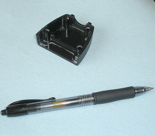
Sample Scan Part
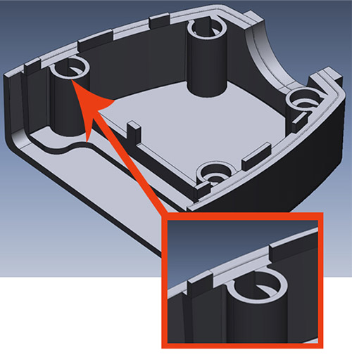
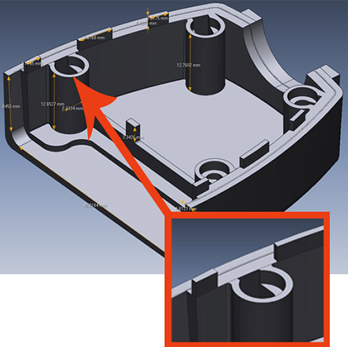
This sample part is a cable connector housing about 2” x 2” x .5” in size. It was scanned with one of EMS’s high resolution 3D scanners. Below is an outline of the different data formats that can be delivered.Contact EMS to receive the 3D scan and CAD data of this connector as described below.
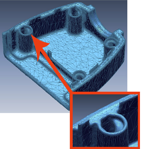
Polygon File
File Format: STL, PLY, OBJ, VRMLDescription: A polygon file is a mesh file consisting of 3 sided triangles and a normal vector. Polygon files are the first step in the scanning process. The final polygon file will be “watertight” and the mesh optimized. Polygon files are good for “organic” free form shaped objects. They can be imported into animation, rendering and any software that can work with a polygon file. Many CAM software programs can generate a CNC cutterpath from a polygon file. Most mechanical CAD systems can NOT work with polygon files to make changes to the model.
Pros:
- Lowest cost option
- Perfect for animation & simulation
- Many CAM programs can machine direct from STL
- Good for organic free form shape models like sculptures, artwork and archeological applications
- Not easy to work with in CAD software
- Files can be very large
- Making design changes can be difficult without special software (SensAble, 3D Max, Maya, etc)
- Sharp corners, planes, holes and other features may not be perfect
Surface Model
File Format: IGES, STEPDescription: A surface model is generated from a water tight polygon model. A surface model contains mathematical information that can be used in most CAD/CAM systems. This format is very useful for organic free form shape models such as boat hulls, automotive body panels, sculpture and more.
Pros:
- Modest price
- Great for free form organic models
- All CAM software can use the data
- All CAD systems can import and work with a surface model but may have limits in editing the data
- Surface “patches” are random
- Limited editing capability in many CAD systems
- Sharp corners and holes may not be perfect
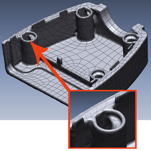
Feature Based Solid Model
File Format: IGES, STEP, ParasolidDescription: A feature based solid model is generated by recreating the model similar to most solid modeling CAD systems. The difference is the input information is the raw scan data. This process allows for the exact recreation of all features including sharp corners, holes and other features. The finished model can be compared to the raw scan data for accuracy.
Pros:
- Best for “mechanical” type parts
- Accurate representation of part
- Model can be edited in most CAD systems
- More expensive option
- More time consuming to generate a finished model
- Not useful for organic free form models
- Some editing limitations in some CAD systems
Parametric Feature Based Solid Models
File Format: SolidWorks, Pro/E Wildfire, Siemens NX, AutoCADDescription: A parametric feature based model includes additional information including dimensions, parametrics and the history tree. This is done by using a “live transfer” that recreates the model step by step in the native CAD system.
Pros:
- Model is usually fully editable in the supported CAD systems
- Most time consuming to create
- Most expensive option
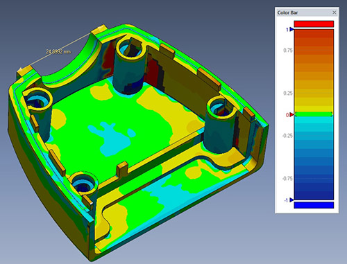
Inspection Report
File Format: PPT, PDF, Excel, XMLDescription: An inspection report gives you a very detailed analysis of 3D scan data. This inspection report can compare the 3D scan data to a nominal CAD file, or other scan data,
Pros:
- Extremely detailed report capturing millions of points on a part. Great for complicated and organic shaped parts.
- Not as accurate as a CMM. Not the best choice for prismatic features (holes, threads, etc)